Tentacle Rig

I began by creating a box. I made it 9 high.
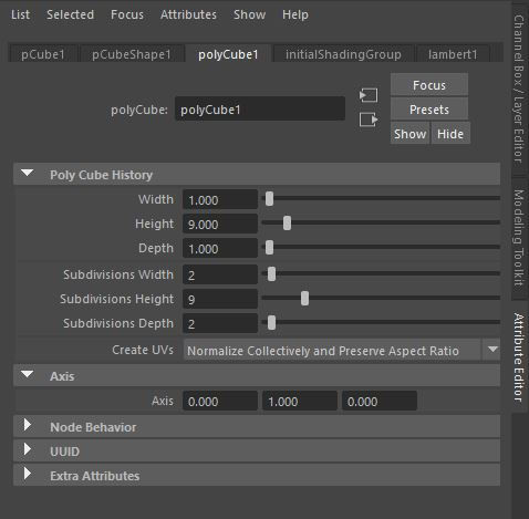
These are the settings i set for my cube.

I moved the pivot point to the bottom of the cube.
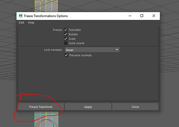
To set all the positions of the pivot back to zero I clicked on Modify, Freeze transformations and i clicked on the little square to bring up this menu. I then clicked on Edit > Reset transformations. Finally i clicked on freeze transform.
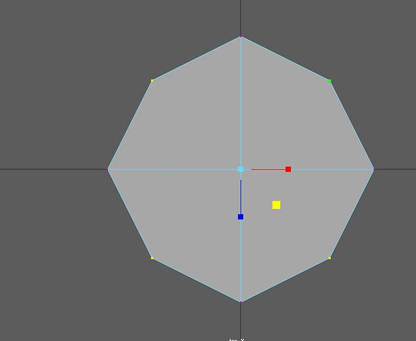
Using the top view i selected the the edge vertices and manipulated them to create a circle shape.

Pressing B i am able to changed the shape of the object in a large mass. I reshaped the object to resemble a tenticle.

I created the skeleton of the tentacle by going to Skeleton > Create joints. Then by pressing X i was able to fix the joints onto the lines.

Next i bound the skin to the model. by going to Skin > Bind Skin. I then selected the small square. I then clicked on Edit > reset settings.

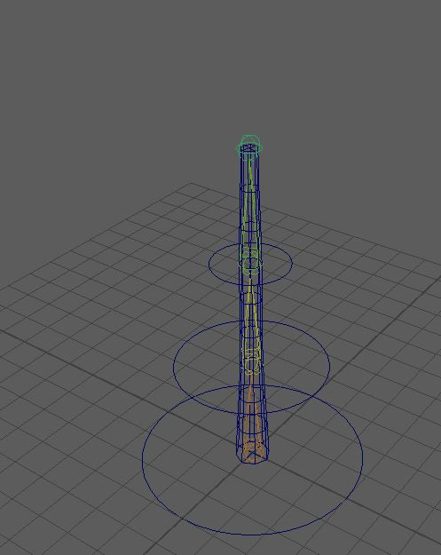
I added in three circles and set the up to look like a Christmas tree. i pressed x to snap the circles to the correct positions.

I parented the joint to the master control.
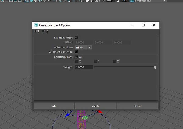
I went to Constraint > Orient, i then clicked on edit then reset settings. I then ticked the box Maintain effect. I then clicked at. I also selected the pivot i wanted to edit. I did this for all the pivots.

I then parented all the circles in the order shown in the image.

I right clicked on the rotate section in the attribute editor and clicked on Create expression. I then wrote the expression on the screen. This will repeatedly rotate the tenticle.
This is how the tentacle looks with all the expressions on.
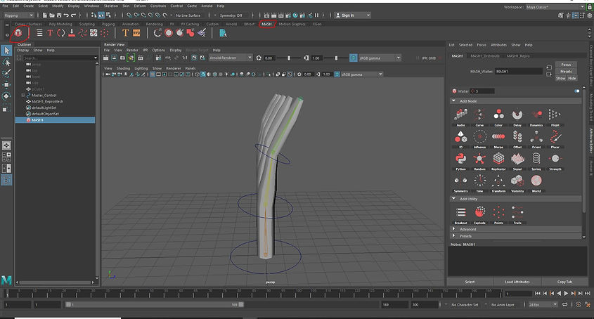
I clicked on the object itself as this next part will not work unless the object is selected. I then clicked on the mash tab and then clicked on the red cube. This created 10 new tentacles. it also allow me to do a lot more things with the model.
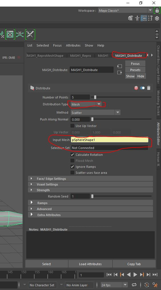
I changed the Distribution type to Mesh and dragged and placed a sphere as the input mesh.

This then created this.

Using the Mash editor i was able to create multiple objects whilst only having one in the scene.

The different mesh i used was Color, Signal and Time. ignore the Flight shape one ad that is not necessary. The color node changes the colour. The time mash allows me to control the animation and the time in which the animations happen. The signal mash effects the movement of the objects within the scene.
Robot Rig

I downloaded this model.

I created the joints by going to Skelenton>Create Joints.
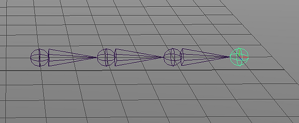
On the floor I created a straight set of joints.
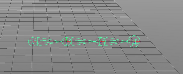
By selecting the first Joint it selects all of them.

By selecting the move tool I then Clicked on the small square between all the X, Z and Y movements. I then went to the area I wanted to snap the joints to and I pressed the Middle mouse button.
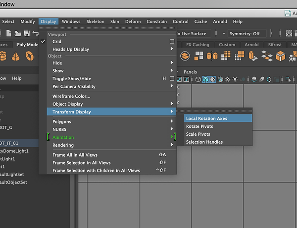
`I clicked on Display>Transform Display> Local Rotation Axes this brings up the centre of the circle.
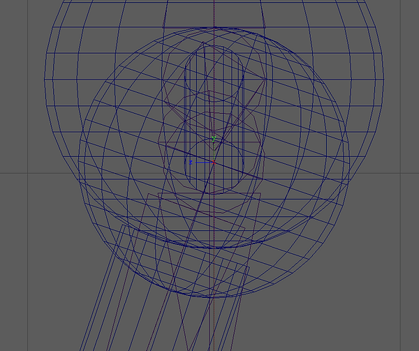
Using the side view i was able to place the first joint in the correct position.

I selected the first Joint and using the rotate tool i rotated the joint so the second one is in line with the knee.

Using the move tool i moved the second joint so it was in the centre of the knee.
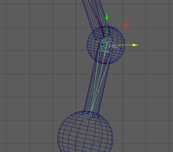
Using the same technique as above i placed the third joint in line with the ankle. I also deleted the 4th joint as it was needed, the reason i created four in the first place was because it is always got to have one extra just in case.

I named these joints as well. This is good to keep everything organised also it will be useful later.

I used the workflow above to create this skeleton. I made the arms and spine. I then mirrored the other leg and arm. I went to skeleton>Mirror Joints.

I selected the whole arm joints.

Once i clicked on Mirror Joints. These are the settings i used. I did this for the leg aswell.
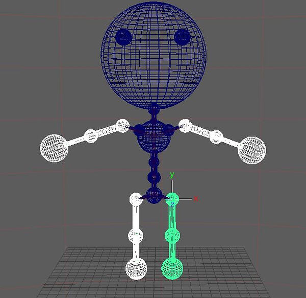
To allow the robot limbs to move with the joints. I had to parent the area to the joints.


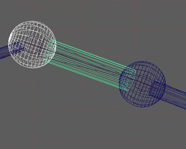

The images above show the order in which the arm needs to be parented. The legs are also the same.

The chest area of the robot was connected to the shoulders, which where shaped to the arms. The arm was connected to the shoulder.
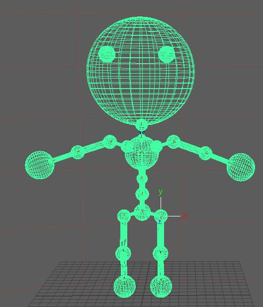
The Legs connected to the waist which then connected to the spine then the chest.
Arm Rig
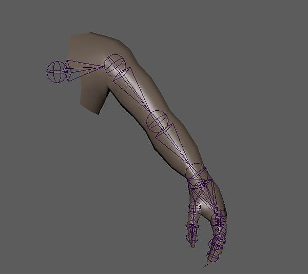
I began with this arm rig

I went to Skin > Bind skin I clicked on Edit and clicked reset settings. Once i had done this is clicked bind skin.
I created an animation using the joints in the arm.


Using a dope sheet i separated the fingers into different times on the timeline. I would select the finger i wanted to move and then used the middle button on the mouse to move the animation.

Clicking on the skin of the arm i right clicked and clicked on Paint skin weight tool. which brought up what you are seeing in the image.
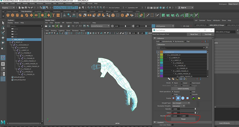
I then clicked on flood.

I locked up all the areas of the arm apart from the top 2. i then clicked on the select tool. I then selected the hand.

I selected higher up the arm and then clicked on the shoulder icon on the right i then clicked on flood.

I clicked on the smooth option and selected the area to smooth the white paint area onto the shoulder.
Rigging controls, robot

I began with a sphere and a cube. I selected the cube and went to the Animation section then i selected Key > Set driven key. With the cub selected i clicked on Load driven.

I then clicked on the Sphere and clicked on load driver.

I then clicked on key

I selected the sphere and moved it u by 4.

I then moved the cube under the sphere and pressed key.

I then moved the sphere to -4 and moved the cube over the the other side and hit key.
This is what i ended up with

I then opened the robot rig and clicked on the skeleton. I clicked on the attribute editor and add attribute.
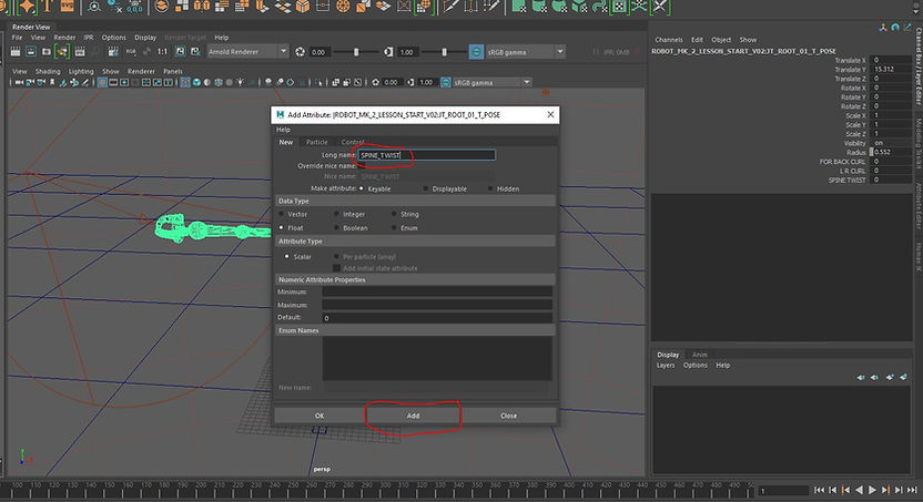
I wrote the name into the Long name tab. Once i put the name in i clicked add.

I wrote out FOR BACK CURL, L R CURL and SPINE TWIST.

I selected the wrist of the robot and selected numb circle 3

I highlighted both of the wrist and Numb circle 3 and hit P to parent the objects.

I then set all the translate X,Y and Z to 0 on the numb circle.

I then rotated the Numb circle and increased the scale.

On the Numb circle I created a attribute called Claw Control i changed the maximum to 1 and the minimum to 0. I then clicked add.

I then created a driven key. The claw control (The numb circle renamed) with the claw control clicked on in the right box.
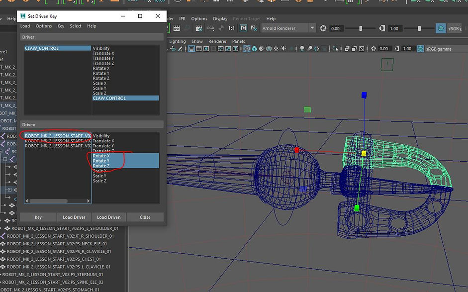
With the Claw control selected i clicked on each Claw with all the rotate option selected in the right box and clicked on Key for each one.

With the claw open and the claw control option set to 1 i set another key. This then allowed the claw to open and close.

I then created a new. Attribute i called this CLAW WRIST. I then clicked on add.
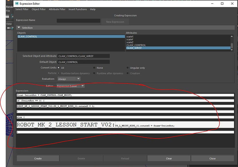
I then right clicked on create expression and i then created this expression within it.
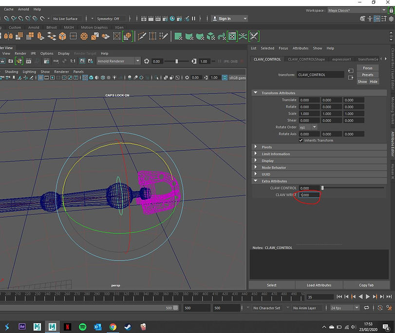
I then clicked the CLAW WRIST and added a value of 1 to it

I placed a dull circle over the shoulder joint.

Highlighting the dull circle and the full arm i then went to Constrain>Orient which opened up the menu shown in the image. I clicked on edit then reset settings. I ticked the box Maintain offset, then apply.

I then duplicated the shoulder circle and placed it over the elbow joint and did the step i did above.

I then did the last two steps with the wrist joint.
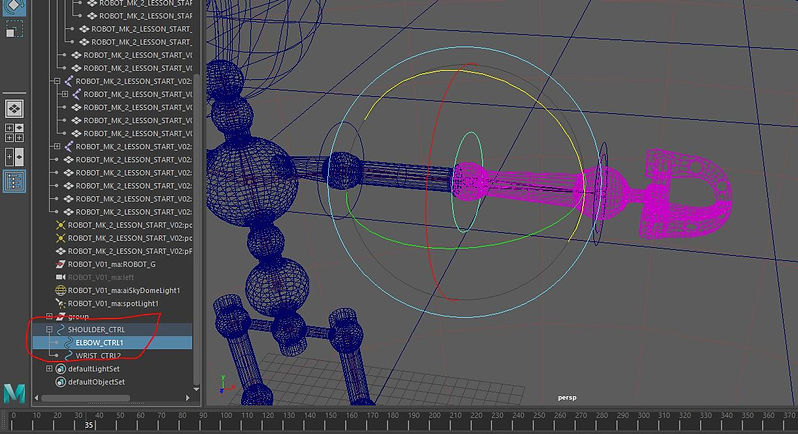
I then parented all the circles together.
Pistons

This is the big piston i made. I began by parenting the the back part of the piston to the shoulder of the arm. i also did this for the other side of the arm with the other part of the piston.

I clicked on the wrist piston and then the Shoulder piston. i then went to constrain > Aim. this meant that the pipes followed each other.

I then parented The end of the spring to the pole it is nearest. I also did this to the otherside.
Spring

I began by creating a helix.
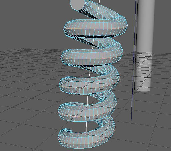
I highlighted the line around the edge of the spring. I then went to Modify > Convert > Polygon edges to curve.
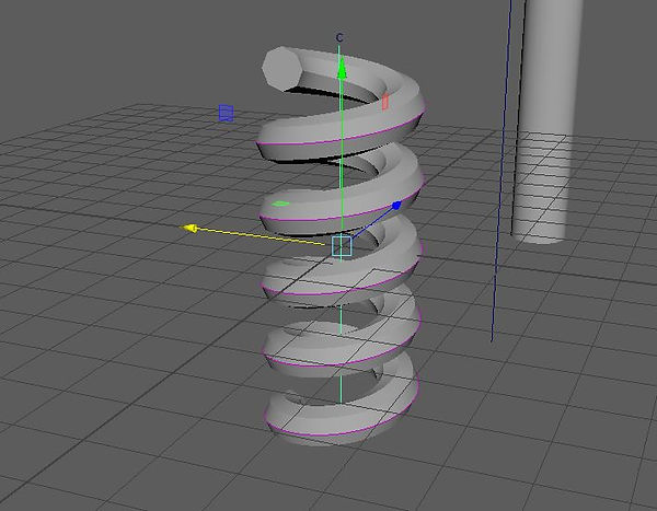
I created a CV curve tool. I did this by going to Create > Curve tools > CV Curve tools. In the settings i turned the curve value to 2. Using the side view is drew out a line through the middle. Right after creating this i selected the spring and deleted all type by history.

I then added a wire to the CV curve. I did this by going to deform > Wire. I then clicked on the CV curve and hit enter. I also selected the Helix and pressed Enter.

Under the Wire tab in the attribute editor. I selected the drop off distance tab and under the Curve 2 option i moved the settings up to a high number.

I highlighted the top point and went to Deform > Cluster. This creates the C

these are the settings for the cluster.
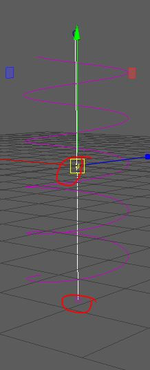
I then created a cluster for each part of the line.
Character rigged

This is a model of a robot that I made. I will be rigging this model.
Joint creation

First of all I needed to create the Skeleton. I did this by creating the joints.

I began by drawing out the joints on the floor. I did this because the joint can only be moved. within the X axis.
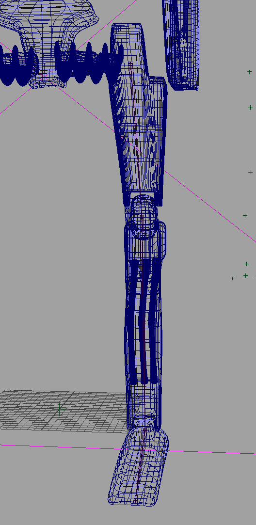
Whilst only moving the joint with the X axis and rotating the joints I ended up lining it up with the leg.
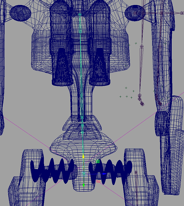
I did the same for the body. Lining it up with the model.

I then did the same for the arm.
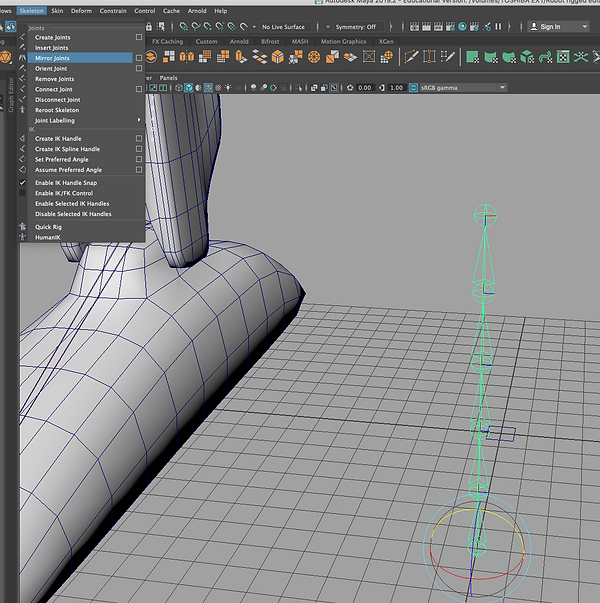
Next I mirrored the arms and legs as it is quicker than making the joints all over again.

These are the settings I used to mirror the joint.

Once Mirrored It placed the joint into the other leg. Sometimes if the character is not mirrored properly like mine then i had to adjust the mirrored joint. I did this for the Legs and arms the Body was just a single skeleton.

Next i need to connect each of the separate Joints. I did this by Parenting the last Bit of the shoulder to the joint in the middle of the chest. I clicked the child first then pressed Shift Left click on the chest joint. I then pressed P to parent them and connect both the joints. I did this for for all the different limbs.

I then created the main control point of the rig. This is so i can easily move my rig around the scene, Increase its scale and rotate it. I did this by going to Create > Nurbs > Circle. This circle i then snapped to the waist joint. I did this by selecting the move tool and then pressing V is then held down middle mouse and moved the Pivot into the middle of the pivot of the Joint. I then parented the joint to the circle.

For the Model to follow the joints i simply parented each Model to the joint it is near.

For the Arms i created an Oriant constrain. This allows the Nurbs circle to rotate the arm allowing an easy control I did this by placing the Circle over the Joint. I then Clicked on the Joint and then the circle i then went to Constrain Orint.

I did this for each joint in the arms.
Rotating Drill

Next i wanted to create a spinning drill. I dd this by creating a Nurb circle. I called it Drill Control.

I then created my own Attribute. I did this by left clicking on the the attribute tab on the top right of the screen. I then clicked on Add Attribute. In the Add Attribute tab i named my Attribute Drill spin. I then clicked on Add. Under the Extra Attributes tab you can now see my new Attribute. I right clicked on this and clicked on Add Expression.

Under the object tab i selected the Drill object. Then Under the Attribute i clicked on Rotate Y. In the expression tab i then wrote the expression that is in there.
Here is a video showing the drill in action.
Head Aim Constraint

Next i added controls to the head. This work flow is the same as it would be for Eyes. I began by adding in a Circle Nurb. I snapped it to the joint within the head and moved it out.

I highlighted both the Nurb and then after the Joint within the head.

With both the Nurb and joint selected i went to Constrain then Aim I ticked Maintain offset and clicked Apply and Add. This then allowed me to turn the head with the nurb.
This is a video showing the head.
IK Handle

Next i rigged the legs. I began with just the skeleton (This image is after i made the IK handle)
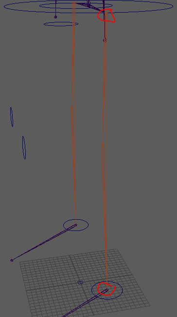
Next i added the Ik handle. I did this by going to Skeleton > Create IK Handle. I then placed the points between the two joint of the leg and then the ankle. The IK joint then acts like a hamstring.

Next i created a control for the knee. This helps me get extra control to the leg. I began by creating a Nurb and snapped it to the knee joint.

Next i attached the Nurb to the IK handle I selected the IK first and then the Nurb. Next i clicked on Constrain > Pole vector.
Here is a video of the legs moving.
Spine control

Next i created the spine control for the character. I began by creating two new attributes Backwards and forwards curl and then LRCurve.

Here comes the somewhat complicated bit. I clicked on Key > Set Driven Key. I then Set the Main control point and set it as the driver. Then the key as the driven. In the driver section i highlighted the Back and forwards attribute i made. Then in the Driven section i selected the Translate Y even tho that should be the rotate Y. I then pressed Key.

In the back and forwards tab i put 4. Then curved the spine then pressed Key. This means if i put 4 into the box it will move the spine. I then repeated this by setting the postion in the box to -4 and i rotated the spine backwards and pressed Key. I then repeated the same workflow but with the LR curve.

I then needed to create a simple way of moving the spine.

I then went to Windows > General Editor > Connection Editor. Then in the left section i had the spine control then in the right section i loaded the main control. In the left section i selected the the Translate Z Then in the right i selected the Attribute i made. This means that i can now move the circle and the spine will move with it. I also did the same with the LR curve.
Final Rig
Here is a video showing the hips and upper boy moving.
Here is the final video of my rig. In this video i just play around with it and move all the limbs.
Shark - rigging and skinned project
I made a shark within Z brush. With this shark i am going to rig, skin and animate the shark to be swimming. Here is a video showing the process of me making the shark. I enjoyed making this. All i need to do now is add teeth once i export it into maya. The shark took me around 3 days (3 hour sessions) 9 hours in total

Cat Spine

To begin with i need to create a curve. I did this by highlighting Skeleton in my tool bar I then went to Create IK Spine Handle. I placed the curve at the second to last joint at the tail. then the second point at the first point of the joint by the head. The curve can then be found within the joint pipeline within the outliner. Next within the Attribute editor under the spline handle i ticked the box Disp CV under the component display.

Changing the settings within the spline is very important aswell. Make sure that the Auto create curve is ticked.

Next i need to create clusters for the different points along the curve. To create a cluster i went to deform and then cluster.

The red dots are the poitns that used to be there. However the clusters cover them up. They allow you to control the spine easier. More then one CV can be put into a cluster.

I created a Nurb circle. I did this by going on create, Nurbs then Circle. I then placed the cirlce into a group and i called it Spine_CNTRL_01_OFFSET_01. I then duplicated this group four times, creating four different nurbs.I then parented each Circle to a Cluster i then zeroed out all the position options which then snaps the circle to the cluster. I then rotated each cluster and positioned it appropriately. I did this for the other three circles. Once all four had been positioned correctly i parented all the circles together this means if i select the last one all the ones before it will move,

I added joints to the the tail.

To skin the tail i selected the tail joints and then shift selected the cat body. I then went to Skin > Edit influences > Add influence. This then adds weight to the skin.
Influences

I opened up a scene with a skinned arm. I parented a sphere to the shoulder joint. I then froze the transformations.

I then moved the sphere down the arm and stretched it out to look like a bicep. I deleted all type by history.

To add the sphere to the skinned arm i highlighted the mesh then the sphere and went to Skin > edit influences > add influence.

I painted skin weights onto the bicep this means that if the sphere bulges then the skin in the arm moves.

Next i went to Key > Set driven key. With the sphere highlighted i loaded it into the driven. I then loaded the elbow joint as the driver. I selected the rotate Y then for the spheres i selected all the scale options.

I rotated the elbow and bulged out the sphere to bulge out the bicep. I then pressed key again.
This is what i ended up with. The bicep bulges when the elbow moves.
BlendShapes

I began with a rig of a mouth. There are three parts to the rig the top part only controls the top lip. The bottom part of the lip i controlled by two joints. The first joint controls the side of the bottom lip and the second joint controls the centre of the lip.

I changed the Workspace to Point Sculpting. This gives me all the options and tools i need to sculpt. I clicked on Create blend shape. With the blend shape selected i clicked on add target to create a target. Then with the edit Highlighted as red i began to select vertices on the mouth and move them into the correct places to create a smile.

I duplicated the first Target by right clicking and selecting the duplicate option. I then right clicked and mirrored the point to move the same target over to the over side.

Selecting both the targets, i right clicked and selected Add combination target. This makes one point control both sides.

Using the sculpting tool, the forth one across upon the tool bar, and I use the tool to smudge the smile and make it look better.

Next I restarted the scene. I created a blend shape within the shape editor. Next i moved over to the pose editor, i selected the two bottom joints and clicked on Create pose interpolater. Next i clicked on add pose.

Next i went to the shape editor. Clicked on the same tool as before and moved the edges of the mouth to create the smile.

I created two Nurb circle The first one i made it into a large, so i can place the second circle into the large one.

Next i began to make to create IK handles, i changed the current solver i changed it to a single chain.

I then placed the two IK handles in the two bottom joints.

Next i parented the IK handles under the appropriate nurb circle. I then parented the small nurb circle under the large one.

With both of the bottom joints selected i created a pose interporator.

Next i clicked view and clicked on advance Clicking on edit within the driver section i dragged the transfer X, Y and Z to into the box and clicked on add. I did this for both of them. I bring up the advance attributes i clicked on display and ticked advanced attributes.
Eye - Lid

Now i am going to use the methods i learnt to create an eye lid opening and closing. I began by creating two blend shapes. a standard one and then a second one for the blink.I selected the vertices from all the first 5 points around the top lid. by pressing B i am able to move the the model without disturbing the model.

Next i moved the pivot point to the middle on the eye lid. I next rotated the eye lid down and positioned it so it was close to the eye lid.

once the top eye lid was positioned well i moved onto the bottom eye lid and did the same as i did with the top eye lid.

Finally, within the Target it placed the slider at 0.65. I then right clicked and clicked on Add an between target. this means the bottom lid wont move up until the slider gets to the point. Using the eraser i deleted the movement before 0.65 meaning the lid wont move.
This is the final result
Sub - pivot control

I began by placing an IK handle in between the shoulder and the ankle. This acts as a hamstring.

Next i changed the IK handle to a single-chain solver. I placed this inbetween the ankle and the foot.

Inext placed the same IK handle in between the foot and the toe

Next i parented all the IK handles under the paw control.

I grouped the toe Ik handle within the Toe_Tap_G and i grouped the Ankle and leg IK in the Flex_G each time the pivot point moves and i have to move it back to the foot joint.

These are all the IK handles within there groups.

Next i created attributes i did this by selecting Attributes > Add attributes. I added in a name in the long name option. I then clicked add.

Next i added in an elbow control. I did this by selecting the circle nerb and the elbow joint. I then clicked pole vector.

I began by placing an Ik, i placed it on the shoulder and wrist. I then created a Nurb circle I parented the Ik to the Nurb.

I next created a Distance tool, i did this by going to Create > Measure Tools > Distance tool.

I placed the distance tool between the shoulder and the wrist. I parented the first locator under the shoulder and the second under the nurb circle.
Fur

I began by importing the character i was going to be adding fur to. I added this character by selecting Windows > General editors > Content browser.

I created fur by opening the groom editor. Then whilst i had the the mesh selected i clicked on create then Interactive groom splines. I then applied the settings i have on screen. These settings determine the amount of hairs and there size.

These are the hairs after i created them.

Next i added a mask i did this by clicking on the base layer. I then clicked on the pen next to the density mask option. I applied the mask to the head, hands and feet.

I applied the mask to the hands, feet and head.

Due to some areas of the model not being masked properly from the standard brush tool. I took the image into photoshop and coloured in the areas that are black with a black coloured brush. I used a UV snapshot to help me with this.

I added a guide layer by clicking on Add modifier > Guide. Then within the guide tab under Input guide i clicked on create. This then creates guides. These guides make all the hair around them move with them.
In this video i use the comb brush to move around the hairs in a realistic manner.

After playing around with different brushes i ended up with this. I used the comb brush, Length and part brush. i created a separate layer for all of these, this means you can turn the layer off and see what different it has made.

Once i was happy with the basic hairs on the model i added a clump. I added a clump by going to Create > Add modifier > Clump. This then clumps up the hairs.

There is many setting with a clump, the most important one to us is the Density slider.

To get the correct data from the clump i had to go into the Node editor I opened it by going to Windows > Node editor. I got rid of the skin graph as i didn't need it there.

I found the two nodes called Clump and inGuide_Shape. i then connected Out Spline Data to the input points. Then within the Extra Attributes i ticked the two boxes that where named Use input points and Preview colours.

Next i added in a second clump and put the settings of the density up to 60. On the first clump i turned the clump down to get more of a fur look.

I then added in a noise modifier
Badger Assignemnt

I began by creating a badger within Zbrush. I then exported it to maya

Using the methods i used earlier on in this module i added joints to the character.

selecting the joints first and the mesh second i then went to Skin > Bind skin. This then turns all the mesh into a skin around the joints. The mesh will now follow the joints, However the weights are not very accurate so we had to go in there and edit them.

To edit the skin weights i started with the base layer. I locked every layer apart from this one and then clicked flood. With the base layer open i then unlocked each layer and selected all the vertices. I then clicked flood. This takes away the paint weight from the base layer and onto the other layer. I then selected the area in between each other and then selected the flood option and then flood. This smooths out the weights in-between the two joints. Meaning the mesh moves even between them.
I skinned every part of the badger, the easiest parts where the isolated areas like the legs and tails. However, every part of the body from the root joint to the head kept on messing up. The skin weights would appear on the wrong parts of the body. How i overcame this way by looking at each body part and deciding which skin weight was meant to be where. Then if for example the shoulder joint had area painted on the neck i would put my courser over that body part in the paint skin weights tab then press right click > select vertices. This then allows me to view every vertice that joint controls. I can then select all the areas i need and then flood the area it is meant to be. This is not the typical workflow but i must have made the mistake of not locking up the layers that i was not using resulting in the areas i didn't want to be painted.
Spline IK

Next i added a spline IK to the spine joints of my model. I added this by going to Skeleton > Create IK spline handle. I placed the first point on the spine joint just before the base joint, i then placed the second joint on the joint in front of it.

Within the settings of the IK spline handle tool It is important to turn on the Auto Create curve.

Using the vertices on the curve created from the Spline IK handle i selected two of them. I then went to Deform > Cluster. This cluster then controls two of the joints. I did this for the other side aswell.

I next created a nurb circle i renamed it SPINe_CNTRL. I then grouped it with the group sharing the same name. With the nurb circle in the group i parented the group to the cluster. Within the attribute editor i zeroed out the rotation values. This snaps the Nurb circle to the point. I un-parented the group then i rotated the nurb within the group 90 degrees. These nurb circles then control the spine.
In this video i move around the spine controls to show what they do.
Stretch and squash controls

I began by adding in a IK handle, a standard one. In between the shoulder and ankle joints.

Next i changed the type of IK handle i was adding in. i changed it to a single chain serve and applied it in the foot and toe joint.

Next i added in a nurb circle and adjusted it to the shape of a paw. The next step i grouped both of the IK handles into a group. I then parented the group to the the paw control.

The back legs are different to the front as there is more joints in the back legs. The workflow is the same as the front paw with the first two steps being the same. However i added in an extra Single chain IK.

The grouping is different this time with there being two extra groups. The first IK is grouped with the second IK in a group called Flex G. The last IK is put into a group by itself named Toe tap G. Then finally both of the groups are then both put into a group named Twist Gw.
Here is a video of me moving around the legs after adding the Ik handles.
Fur

Then finally i have added fur to the badger. AS i said before i began by changing the work space to Xgen - Interactive Groom. XGen is very useful when it comes to adding fur.

Adding fur to the badger is the same with the alien. i clicked on create > Interactive groom splines.

Once i had added the first bits of hairs on my model i then created the Mask. The mask is useful for stopping hair from appearing on areas you do not want them to. To create the mask

To Add a mask i went to the Badger_Base tab and clicked on the brush next to the density mask

Because there are gaps that tend to be missed with the brush tool in maya i had to take the map of the Mask and colour in the black areas making sure there is not gaps.

I added guides. Guides make it easier to brush a large area of fur, this is because the guide controls all the hair in the area around it. I added them by pressing create, which in this case has delete but that is because i have already made them.
In this video i use the comb brush to move around the hairs into the position i want. This means if you increase the size of the heads and the frequency then they will grow in that direction. Plus it looks neat aswell. A big issue i did come across is due to my model having four legs very close to each other the brush moved the hairs on the other legs and i had to keep on going over it again. This can lead to bold patches. which do not look good. An area on the model i struggled to stop the bold patches was the hips of the back legs, every time i tired to move them out it would mess it up even more.

Eventually after brushing the hairs for a while using the comb brush. i ended up with this. It looks good but there is still some bits missing. So next i add a clump this as the names says clumps up the hair.

This is what the clump does to the model. However to get a proper effect from the clump and create realistic fur we must go into the the Node editor, within the node editor I found the two nodes called Clump and inGuide_Shape. i then connected Out Spline Data to the input points. Then within the Extra Attributes i ticked the two boxes that where named Use input points and Preview colours. Next i added an extra clump. i then turned up the Density to a really high number. This then makes small clumps instead of large ones.

The second clump Creates these small clumps that look more like actual fur.

These are the settings for the second clump. The density is super high to create the small clumps. I also added in a noise Modifier This makes the fur scruffy and creates random stands of hair.

I took a screenshot of the UV layout, i did this so i can take it into Photoshop and add colour to the layout and apply it to the model. To apply a matirial to the fur i slected the Badger Xgen layer in the Outliner and then right clicked > New matirial > Arnold > AIarnoldFur. I then applied this map to the colour part of the material.

Here is a render of my honey badger. I added an Arnold light. The light i added was the Physical sky. This is because it gives an overall view of the whole object. There are a few bold patches that i couldn't fix. Each time i tried to pull them out it would effect the whole area. I got the bold patches to the smallest i could.
Rendering

I added in a Physical sky. This is because it gives an overall lighting around the whole object. To get this light i went to Arnold > Lights > Physical sky.

Next i increased the Samples to 3. This means the shadows has less noise in the shadows.

I went into the render settings and adjusted the Sampling. This increases the quality of the picture. There is less noise in the fur. I increased the Camera from 3 to 6. The Camera option increases every other option. I also increased the Diffuse and specular from 2 to 3.

This a render with the options i said about above increased, it certainly looks a lot better. I am disappointed with the bold patches. But this is my firs time using the Xgen fur. i will certainly be practising with Xgen as i have enjoyed using it. Sadly i did have to reduce the settings for the final render as each frame was taking a long time to render and because of time i couldn't render it with the high settings.
In this video I show all the techniques i have added to my rig. It shows the fur reacting to the light. plus the fur moving with the skinned model. I start of by moving the front leg using the IK stretch and squash control. Next i move to the back leg that has the same controls on it. I also demonstrate the spine IK i added. Sadly due to crashing this is not the full clip of the rig moving I also added in neck movement and the other section of the SpineIK. Overall i enjoyed this module but found it very challenging, I am certainly going to be practising with the skinning and rigging as it is something i wish to improve at.
In this video i show the different rigs i added to my character. I have turned the fur off as it lags to much with it on.
Bi- frost

I began with a mesh

Next i clicked on the mesh and then went to Arnold >Utilities > Render to texture. This then renders the texture and makes it into a image file. we will use this later.

I then went to Cache > Alembic Cache > Export selction to Alembic. i clikced on the settings box. I then ticked UV write and write colour sets. Next i clicked export selection.

I then deleted what i had and went to Alembic > Import Alembic. I selected the file I made.

Next i opened the Bifrost graph. I then imported my mesh and connected the Mesh output to the input of the output node.

By pressing tab i am able to bring in different nodes. I brought in a source MPM snow, Simulate mpm, a Colider and a Mpm solver settings.

Next i applied the mesh pipeline into the geometry of of the source mpm snow. I then i applied the mesh pipeline of the colidershape to the geometry of the collider. Then finally when i try to apply the Granular particles of the simulation mpm to the output node there will be an error but if it right click and delete port of the output node and delete the bif in the outliner it will fix it. after this i set the colliderdetail size to 0.15. i also selected the mesh right clicked went down to paint and selected the standard texture. I then changed the colour type to RGBA and imported the texture back in.

I brought in a set_property node. i right clicked on the value node i then clicked on value. In the key tab i put in color. then with the set property selected i clicked on Mesh display > color set editor and i changed the name to color. i then connected outobject of the set_property to set_particle_properties of the source_mpm_snow.

I then clicked on the source snow mesh. i changed the start frame to 33. and the end frame 33. i do this so the particles do not start falling until that time frame. also i changed the Y axis to 01 and the Z axis to 1 in the direction option.

Next i brought in a file_Cache. now this bit is confusing. I went to the project folder where i went into the Cache folder. I made anew folder called BOB i then made anew folder inside this one called Antonia. I wrote Antonia into the file name after bob. I then copied the file path into the first part of the file name option. i then connected the objects pieline from the cache node to the granular_particles of the Simulate node. I then connected the out_objects of the file cahce to the output node.

This is where i got before i got stuck and couldn't fix it. I think the file pathway is broken so i will go back through and fix it later. but this is my current pipeline.